Quite often in the voice world we are pointed at and told that our system doesn’t work, call quality is poor, the caller’s voice drops out, calls are being disconnected randomly etc. Then we have to go and decipher what is really going on and isolate the issue so we can determine where the fault lies within the network… or perhaps outside the network.
Rcvr Lost counter on an IP Phone simply states that the phone expected to receive x amount of packets and only receive y amount of packets, the difference being the RCVR Lost counter. How does the phone know what to expect? Well RTP is a stream of organised sequential packets, each packet has a sequential number associated to it.. If RTP packet number 1002 was lost along the way, then the phone would receive RTP packet 1001 and then 1003… the phone would be asking.. Hey where was RTP packet 1002? And then notch up the RCVR Lost counter. With enough packets lost in a RTP stream.. The callers now start to experience poor quality with words dropping out etc.
Of course this is our problem until proven otherwise, Telcos never want to investigate into the problem first.. I’ve outlined the process of what I undertook to essentially clear the phone system of any wrong doing and force the Telco to take a closer look at the issue.
First of all, this is a SIP ITSP connection.. I have a Cisco 2901 ISR acting as a CUBE, with CUCM sitting behind the CUBE.
1. Enable web access to the phone. View the phone from the web and select stream 1. This is the primary conversation. There will be a few counters in here.. But we interested in RCVR Lost counter and the customer is complaining about not being able to hear callers, as their voice drops in and out, hence we look at the incoming stream. If the RCVR Lost counter has any number higher then ’1′ then we have a potential issue.
2. Now lets log into the CUBE. We are looking for packets received and packets sent for the call conversation. These should exactly match the phone. Use the following command on the CUBE to view packets in / out. HOSTNAME# show call active voice brief

In the above output, you can see between the Inbound and outbound call legs (same Call IDs), the rx (received) packet count on the inbound call leg exactly matches the tx (transceive) packet count on the outbound call leg. (The yellow highlight represents the call flow inbound and the Red underline represents the call flow outbound.
When the rx and tx are matching, this indicates the CUBE is not dropping any packets in the RTP stream. So we must look further out to the Telco.
4. Also check the Switching interfaces for lost packets, this is quite rare, but worth verifying to ensure switch ports or QoS are not dropping packets etc.
5. Lets take a packet capture on the outside interface of the CUBE. We want to do this to explicitly identify if the any RTP packets have been lost before arriving at the CUBE. We can also playback the RTP stream in wireshark to listen for the defect in the voice.
6. To capture packets on the CUBE follow the below. There is also a great article, which I have linked below that expands on capturing packets.
(config)# monitor capture buffer BUF size 2048 max-size 1518 linear
(config)# ip access-list extended RTP
(config-ext-nacl)# permit udp any any range 16384 32767
(config-ext-nacl)# permit tcp any any eq 5060
(config-ext-nacl)# permit udp any any eq 5060
(config)# monitor capture buffer BUF filter access-list RTP
Select the interface of the capture point. Also select the switching plan.. Which should be cef and not process.
(config)# monitor capture point ip cef POINT gigabitethernet 0/1 both
(config)# monitor capture point associate POINT BUF
(config)# monitor capture point start POINT
(config)# monitor capture point stop POINT
(config)# monitor capture buffer BUF export tftp://10.1.1.1/BUF.pcap
Delete capture point and capture buffer
(config)# no monitor capture point ip cef POINT fastEthernet 0 both
(config)# no monitor capture buffer BUF
7. Now we can open the stream in wireshark. If the stream is g711u/alaw then wireshark will have no problems analysing the RTP stream and playing it back to you. If the stream is G729 however, I’ll add a note onto the bottom of this blog to take you through decoding g729, actually I’ll add this is as a separate blog entry.
8. Open the PCAP file in wireshark. Navigate to Telephony -> RTP -> RTP Streams. This will display the captured RTP Streams.

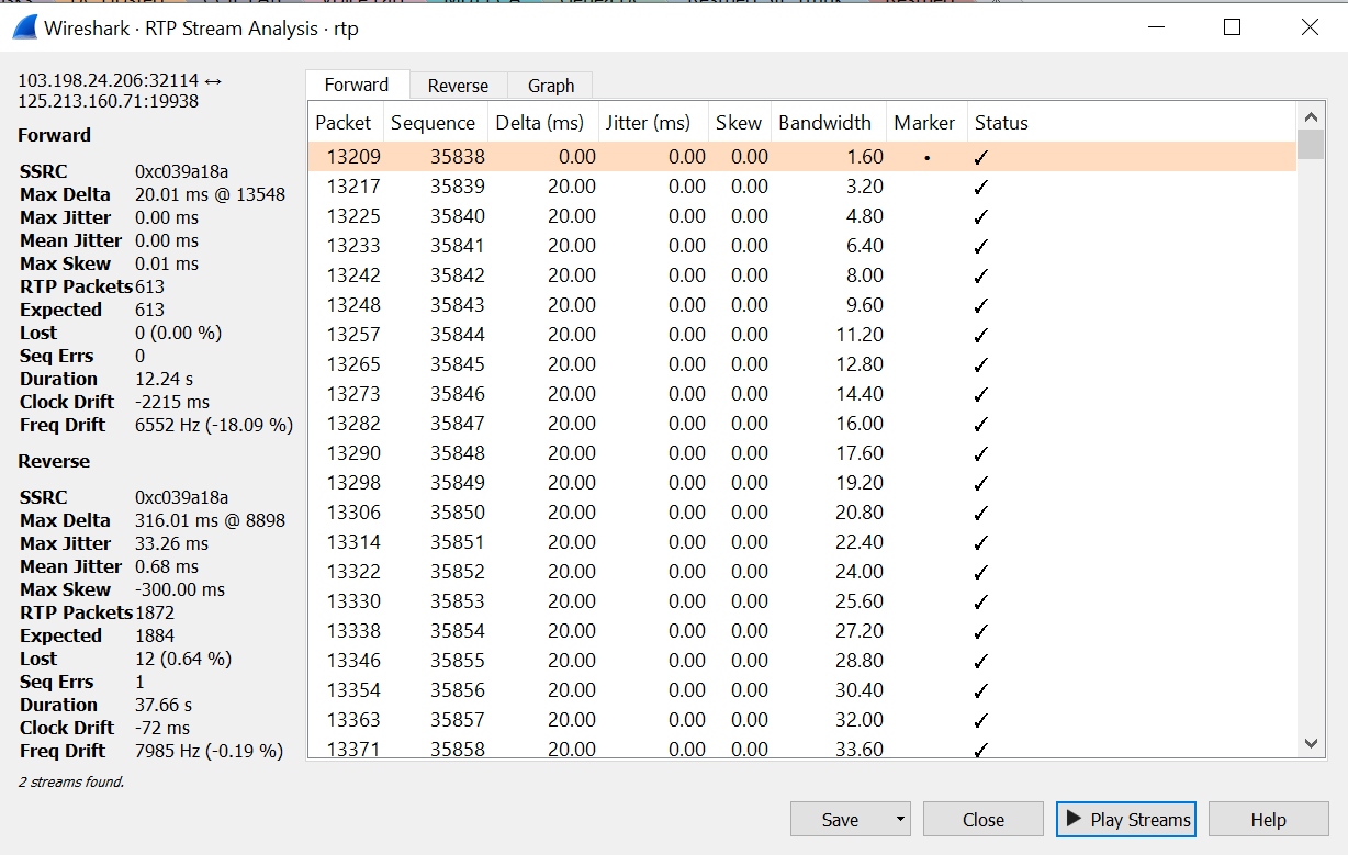
We can also see from here that the inbound call leg for the external facing interface is displaying lost packets and a high jitter number. These lost packets are known because the RTP stream is sequential.. Hence the CUBE knows how many packets it should have received vs the packets is has received. In this case we can send this result to the Telco as this definitively states the issue lies before the one-premise CUBE processes the RTP Stream.
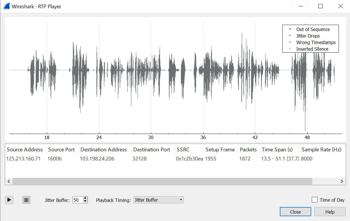
We can also play the stream to hear for any missing voice etc. Select the ‘Analyze’ button. This will display a window with more statistics for the RTP Stream.

No select Play Stream. This will playback the stream.

Link to capturing packets on Cisco IOS Router.
www.cisco.com/c/en/us/support/docs/ios-nx-os-software/ios-embedded-packet-capture/116045-productconfig-epc-00.html


