Apr 28

Active Control and Cisco Meeting Server – Mute

Cisco Meeting Server provides a more feature rich conference environment with Active Control enabled. Not only the does the CMS Server need the SipUDT flag enabled (enabled by default), the Call Leg Profiles needs to have the feature enabled, the codecs need meet firmware versioning minimums and have the Active Control flag set to Auto as well as CUCM will need to have the relevant SIP Profiles sending the Xi Parameter for Devices and Trunks. Tracing Active Control is done via SIP and Active Control XCCP Packets, I’ve outlined below some key components to tracing Active Control Features. Below is an example of the Codec Muting and Unmuting itself. The unmuting will reflect the change in the rxAudioMute flag on the CMS Server, which is turn reflects the Microphone Unmuting in the CMM Management Screen. Also, worth to note, the below output is also based on ‘Linked’ Mute Behaviour as opposed to ‘Separate’ Mute Behaviour.

Scenario:

  • Multiple Call Bridges in a single Call Bridge Group with Load Balance enabled
  • Cisco SX20 Codec operating 9.15.X firmware.
  • Call Bridge version is 3.2.1
  • CUCM version 14 SU2
  • Direct routing between CUCM and CMS
  • Call Leg Profile is set as below
    • rxAudioMute = True (Mute on entry)
    • muteSelfAllowed = True (Allow Codec to unmute/mute as required)

Call Flow:

Codec -> CUCM -> CMS -> CMS

Codec dials into Space directly, CUCM sends a Delayed Offer to the landing point is which is CMS01. Load Balancing is then conducted, CMS02 Call Bridge is voted to host the conference. CMS02 then places an outgoing call to the Codec, hence sends a SIP INVITE to the CUCM. CMS01, will CANCEL the original SIP INVITE from the Codec/CUCM.

So, the within the SDP, there should be a couple of attributes to the tune of..
m=application 30419 UDP/UDT/IX *
a=ixmap:0 ping
a=ixmap:2 xccp

This is the Active Control negotiation within the SDP. If these lines are not present, then CMS is not enabled for Active Control. Vise versa.. If CUCM sends the 200 OK SIP Msg without the above attributes, then CUCM Sip Profiles do not have Active Control configured.

Active Control Tracing on the CMS will not show the Active Control State of the call via the b following line ‘ActiveControlState change, unknown -> negotiating’.

<?xml version=”1.0″ encoding=”UTF-8″?>\n
TX: <request type=”subscribe-capabilities” id=”1″>\n
TX: <subscribe-capabilities min-interval=”5″>\n
TX: <expires>1800</expires>\n
TX: </subscribe-capabilities>\n
TX: </request>\n
call 4942: need to start new conferencing link for XCCP
call 4942: starting up conferencing link for XCCP
call 4942: starting up conferencing link user for XCCP
call 4942: incoming XCCP message, size 197:
RX: <?xml version=”1.0″ encoding=”UTF-8″?>\n

Active Control Feature and Capabilities will now be negotiated between the CMS Call Bridge and the Codec.

CMS Call bridge will not set the feature capabilities upon the Codec. Below snippet is the Call Leg Parameter ‘rxAudioMute’ being pushed down to the Codec. (Also, within this same xml msg, the parameter ‘rxVideoMute’ is also pushed down to the Codc)

call 4942: outgoing XCCP message, size 684:
TX: <?xml version=”1.0″ encoding=”UTF-8″?>\n
TX: <notify type=”acked-self-info” notifyId=”4″>\n
TX: <self-info>\n
TX: <user id=”e0d5c105-5b68-44bd-85a6-3c3b2f23a749″ entity=”91021@justice.nsw.gov.au”>\n
TX: <display-text>SYD-DOWN-MULTIMEDIA-MR1- 91021</display-text>\n
TX: <recording>false</recording>\n
TX: <deactivated>false</deactivated>\n
TX: <endpoint entity=”91021@justice.nsw.gov.au”>\n
TX: <status>connected</status>\n
TX: <joining-method>dialed-out</joining-method>\n
TX: <capture-source-id>19416111</capture-source-id>\n
TX: <media id=”1″>\n
TX: <type>audio</type>\n
TX: <status>recvonly</status>\n
TX: </media>\n

TX: <media id=”2″>\n
TX: <type>video</type>\n
TX: <status>recvonly</status>\n
TX: </media>\n
TX: </endpoint>\n
TX: </user>\n
TX: <count>\n
TX: <visible>0</visible>\n
TX: </count>\n
TX: </self-info>\n
TX: </notify>\n

At this point, the Codec has successfully joined the Conference, the Call Bridge has set the relevant features upon the Codec. The Codec has been Muted both Audio and Video.

The Meeting Room Operator, can now press the Mute Button on either the Touch 10 or an external Microphone to unmute the Codec.  Below is snippet for the XML Msg sent to the Call Bridge from the Codec.

call 4942: incoming XCCP message, size 225:
RX: <?xml version=”1.0″ encoding=”UTF-8″?>\n
RX: <request type=”self-mute” id=”7″>\n
RX:   <self-mute>\n
RX:     <endpoint entity=”91021@justice.nsw.gov.au”>\n
RX:       <media id=”1″ media-allowed=”sendrecv”/>\n
RX:     </endpoint>\n
RX:   </self-mute>\n
RX: </request>\n

The Call Leg parameter ‘rxAudioMute’ is not set to false and the CMM Server will indicate the Mute is now off from the Codec.

Further Notes to Muting/Unmuting behaviour with Active Control. The CMM Server cannot unmute the Codec. If you attempt to unmute via CMM Console, the microphone icon will switch off for a couple of seconds, then switch back on indicating the microphone is muted again.
Jan 21

Upgrading to Cisco Meeting Server 3.5+

Key notes for upgrading to CMS 3.5+ from 3.4 and earlier is to ensure the database cluster is dissolved prior to the upgrade event. Cisco have introduced enhanced security for the Database Cluster from version 3.5.

Key steps is to firstly identify which CMS Nodes are in the database cluster and also which node is the current Primary Node.

Take backups of all CMS Servers prior to making any changes.

Log into the clustered peers and issue the “database cluster remove” command. After each peer is removed, log into the current Primary Node and issue the “database cluster remove” command.

Now the upgrade can take place for each CMS node.

After each CMS Node has been upgraded successfully to 3.5+, the database cluster will need to be re-established.

Log into the Current Primary Node as noted above and issue the command “database cluster initialize”.

Now log into the remaining CMS Nodes and issue the command “database cluster join IP_Address_of Primary_Node”

One last step is to update the schema. Issue the command “database cluster upgrade schema” from the Primary Node.

Nov 01

Cisco Meeting Server – Part 8: Call Bridge Groups

Call Bridge groups allows call bridges that are clustered to load balance in/outgoing calls, apply the smarts behind load sharing resources. We then link services or functions to the Call Bridge Groups. (as seen is later steps)

1. Using the an API Tool like POSTMAN, create a Call Bridge Group, and store the Call Bridge Group ID somewhere on your PC for later use. The command to use is POST https://172.18.27.24:445/api/v1/callbridgegroups.
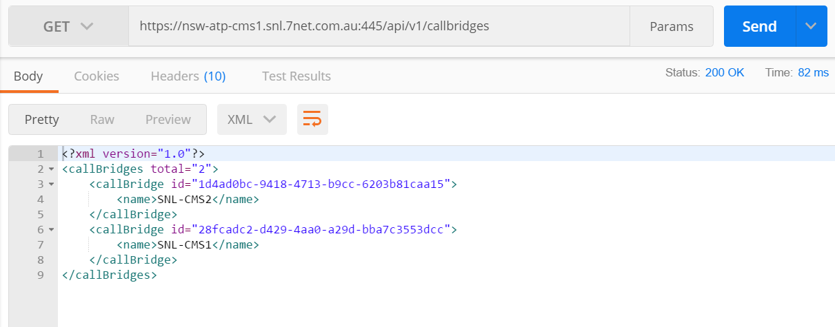
2. Collect the Call Bridge IDs that will be members of the Call Bridge Group using the GET cmd.

cms-cbg-1

3. Modify the Call Bridges to add the Call Bridge Group ID

PUT -> api/v1/callbridges/call_bridge_id/
BODY – > callBridgeGroup = call_bridge_group_id

cms-cbg-2

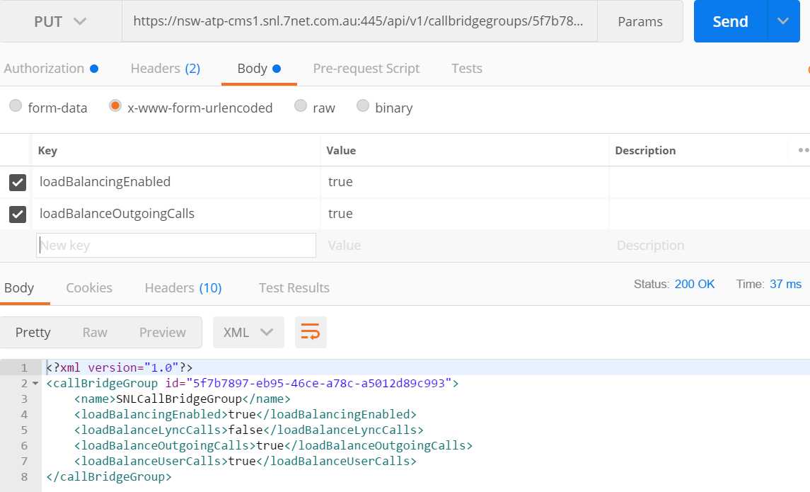
4. Next we enable load balancing for the Call Bridge Group.

PUT -> api/v1/callbridgegroups/callbridgegroup_id
BODY -> loadbalancingEnabled = true
BODY -> loadbalancOutgoingCalls = true

cms-cbg-3

Oct 20

Cisco Meeting Server – Part 7: Call Bridge Cluster

Call Bridges operate as a single entity when clustered, scaling available resources. A prerequisite is to have a fully configured and functioning Database cluster. (Read PART 5 of this blog series).

Two cluster types exist. Peer to peer and via Call Control. Most efficient method is Peer-to-Peer. Where Call bridges route media directly between themselves and not via a call control server (CUCM).

Steps to Configure a Call Bridge Cluster

1. Log into Web Admin of each Call Bridge CMS Server. Navigate to Configuration -> Cluster. Enter a unique name for the Call Bridge. Eg CMS_01 (must not contain spaces).
2. On the first Call Bridge, go to Configuration -> Cluster and add All Cluster nodes into table using the above Unique Node Names. Do not enter the “Peer Link SIP Domain” field. Also ensure the Address is https://fqdn:445 (webAdmin Port). Ensure this address is DNS resolvable!

cms-cb-cluster-1

Another key factor to this configuration is the dial plan. For inter-peer calls.. (between Call Bridges in a Call bridge Cluster), a route must exist for the IP Address for peer members. There is a required when the “Peer Link SIP Domain” is left blank for the Call bridge Cluster.

*If you do not configure these outbound rules, you will see an error “remote media link to call bridge CALLBRIDGE failed for call”.

The impact will see a single video conference that is split between two CMS Call bridges.. Thus the conference participants will only see other participants on that same Call Bridge Host.

cms-cb-cluster-2

Oct 08

Cisco Meeting Server – Part 6: Call Bridges

Now we move onto creating the call bridges within our CMS Architecture. Call Bridges are the work horses.. These guys mix the media streams for conference participants. We will cluster the call bridges in the next step, for now lets setup the base services for the call bridges.

First is to upload the key an certificate files from the above ‘Certificates’ step via SFTP. I name the cert files for the call bridges “callbridge.key” “callbridge.cer”.

The certificate files will be shared among the call bridge servers.. So be sure to upload to each call bridge.

Select the interface for the Call Bridge to listen on. (Typical deployments will have interface ‘a’ selected)

Commands are:

callbridge listen a
callbridge certs callbridge.key callbridge.cer chain.cer
callbridge restart

cms_callbridge_1

*Repeat all Call Bridges

The base call bridge service has now been setup for each call bridge.

Oct 04

Cisco Meeting Server – Part 5: Database Cluster

As with any cluster, there is a master/slave relationship and there is no difference with CMS DB Clustering. We first need to initialise the DB Master, followed then by connecting all DB slaves. Remember.. The CMS DB Cluster must have an ‘odd’ number of members.. Another note to make about cluster members is the Call Bridge doesn’t have to be operational.. Hence DB Cluster members can be on general/standard VMs with typical resource usage such as CPU and Memory.. No need to allocate huge amounts of resources to DB Cluster members.. One example I can give is to have a 2 node Call Bridge Group configured linking to a 3 node DB Cluster.

Configuration steps starting with the CMS Database Master

Attach certificates to the database cluster.. We have already provides CSRs and have signed certificates from previous steps.

From the console enter:

database cluster certs dbserver.key dbserver.cer dbclient.key dbclient.cer chain.cer
cms_database_1

database cluster localnode a (We are specifying the CMS network interface for the DB to use)

database cluster initialize
cms_database_2

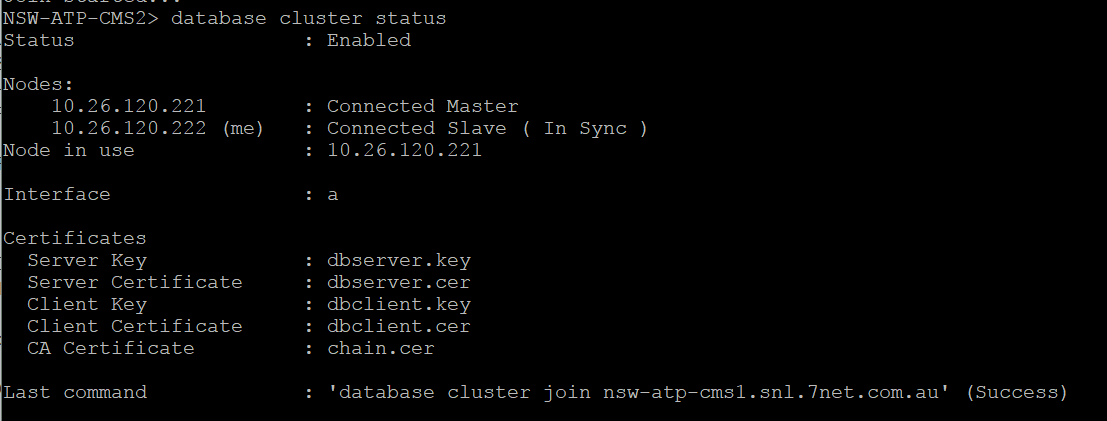
database cluster status
cms_database_3

Now Join each of the Slave Database Servers to the database cluster

Upload via SFTP the below certificate files

- Dbserver.key
- Dbserver.cer
- Dbclient.key
- Dbclient.cer

The above files were generated under the Certificates section. These files will be shared among CMS Servers.

Validate the certificate files on the CMS Server via the ‘pki list’ command
cms_database_4

database cluster certs dbserver.key dbserver.cer dbclient.key dbclient.cer chain.cer
cms_database_5

database cluster localnode a

database cluster join cms_hostname.com.au (this is the DB Master’s hostname)
cms_database_6

Database cluster status
cms_database_7

Repeat for each Slave Database Server. Note: Do not have an equal number of Database Servers in the cluster, must have odd number count. Example Cluster of 3 or 5 not 2 or 4.

Sep 27

Cisco Meeting Server – Part 4: Web Admin Configuration

We are now is a position to start configuring the Core functions of CMS. One of which is the Web Admin to give us access to the GUI.

Ensure, you have copied the webadmin.key from the CMS 1 host to the remaining CMS Hosts. Then also copy the webadmin.cer and chain certificate to all CMS Servers.

From the console enter the below.

webadmin listen a 445 (This allows the 1st Interface to listen of port 445 for the Web Administration portal. We keep this portal off port 443, as we will configure a Web Bridge later for internal webrtc clients.)
webadmin certs keyfile function_certificate cert_bundle (example: webadmin certs webadmin.key webadmin.cer chain.cer
webadmin enable

The CMS server will cross check the Key file matches the Certificate file, and then ensure the Chain Certificate is the actual signing CA Authority.

To validate the webadmin service.. Enter webadmin status.

Now browse to the https://cms1server.example.com.au:445

Sep 20

Cisco Meeting Server – Part 3: Certificates

Certificates are the next step in the CMS deployment. Now with version 2.7+ certificates are mandatory all to be signed by a CA. I’ve listed the functions below that we will generate CSR’s for. A brief description of how to generate the CSR is included. I find it easier to generate all CSRs from a single host, then have the IT Administrator sign all the certificates.. Then I’ll distribute the keys and signed certificates to the appropriate CMS Hosts.

I like to group certificate to functions. Yes, you can just issue a single certificate.. But again, I like to logically separate certificates to functions..

The general command to run is “pki csr function_name CN:cms-host1.example.com subjectAltName:cms-host2.example.com.au,cms-host3.example.com.au

Reboot each CMS Server after licenses have been applied.

Functions

WebAdmin – Standard certificate. I include ALL CMS Servers, including the EDGE (interface a) servers. Use the subjectAltName: attribute for the additional CMS Servers.
Call Bridge – Standard certificate. I will include only the CMS Servers that will host conferences.
Database Server – Standard certificate. I will only include on the CMS Servers that will share the Database.
Database Client – Specific CN for the certificate: CN:postgres Only enter this CN into the CSR. No subjectAltName attribute.
XMPP Server- This certificate will include all CMS Servers that will be a member of the XMPP Cluster. This certificate will also list domains for the organisation, including all domains in a multi-tenancy deployment.
Trunk – Standard certificate. Will include only the CMS Servers that are a member of the XMPP Cluster.
Load Balancing – Standard certificate. I will include only the EDGE servers.

The Chain or Root Certificate

The Cert Bundle is the Trusted Root Certificate. This is required when attaching signed certificates to the various components such as Web Admin. If there is only a single Root CA, then all you need to do is copy the Root CA cert to the CMS Servers via an SFTP client. Then simple reference the cert when activating a component. If there is also an Intermediate CA.. Then you will need to manually create a certificate bundle. To create a certificate bundle, open both the Root CA and the Intermediate CA certificates into notepad. Copy the text of both certificates into a new text file. Root CA text first, then next line add the intermediate certificate text. (no line break), then add a blank (space) line at the end of the file. Save this as a “.cer”. Copy this Root Chain certificate to the CMS Server. Then simply reference the chain certificate when activation components.

I use Filezilla FTP client to upload certificates, download CSRs and keys etc. All certificates, keys etc are loaded into the root directory on each CMS Server.

Run the command pki list to show a list of CSR’s, keys and certificates.

**NOTE: For certificates to be shared among the CMS Servers, copy the cert.key & the certificate to all required CMS Servers.