Oct 01

Ring No Answer Duration – CUCM

Since the introduction of Cisco’s Collaboration Edge environment, I’m seeing more of a requirement to modify the Ring No Answer Duration timer under the Users Line to a timer above 20 seconds. This is because, by the time the signalling routes to the Jabber Mobile Device, the default Ring No Answer Duration timer has a couple of seconds remaining before expiring and forwards the call to an alternate destination, which is voicemail in most cases. I have found between 20 – 24 seconds is a balanced ground between, not having the phone ring too long at the desk and allowing the Jabber Mobile Device enough time for the user to answer the call.

To change the default the Ring No Answer Duration in CUCM, go to the Service Parameters and navigate to ‘Forward No Answer Duration’. Default is 12 seconds. Modify this parameter to 20 seconds.

Sep 23

Download MoH Files from CUCM

To download Music on Hold WAV files from CUCM follow the below CLI commands. This will download all MoH WAV files on the CUCM to your SFTP Server. Once downloaded, you are able use the ‘ulaw’ wav file to upload to a different CUCM Server.

admin:file list activelog mohprep
CiscoMOHSourceReport.xml                Test-AudioTrack_01_2009.alaw.wav
Test-AudioTrack_01_2009.g729.wav        Test-AudioTrack_01_2009.ulaw.wav
Test-AudioTrack_01_2009.wb.wav          Test-AudioTrack_01_2009.xml
Test-AudioTrack_17_2009.alaw.wav        Test-AudioTrack_17_2009.g729.wav
Test-AudioTrack_17_2009.ulaw.wav        Test-AudioTrack_17_2009.wb.wav
Test-AudioTrack_17_2009.xml             Test-IPCCHold_20secs_2009.alaw.wav
Test-IPCCHold_20secs_2009.g729.wav      Test-IPCCHold_20secs_2009.ulaw.wav
Test-IPCCHold_20secs_2009.wb.wav        Test-IPCCHold_20secs_2009.xml
SampleAudioSource.alaw.wav              SampleAudioSource.g729.wav
SampleAudioSource.ulaw.wav              SampleAudioSource.wb.wav
SampleAudioSource.xml
dir count = 0, file count = 21

admin:file get activelog mohprep
Please wait while the system is gathering files info …done.
Sub-directories were not traversed.
Number of files affected: 21
Total size in Bytes: 44978093
Total size in Kbytes: 43923.918

Would you like to proceed [y/n]? y
SFTP server IP: 172.20.20.20
SFTP server port [22]:
User ID: ben
Password: ********

Download directory: /

The authenticity of host ’172.20.20.21 (172.21.30.31)’ can’t be established.
RSA key fingerprint is 0c:86:dd:98:e4:76:52:ac:a6:92:d8:97:8c:8c:df:31.
Are you sure you want to continue connecting (yes/no)? yes

…………………
Transfer completed.

Aug 05

Informacast Paging Basic Setup with CUCM

Informacast Paging UCM Edition Basic Information

- 50 members maximum in a recipient group.
- Can have multiple recipient groups
- Can have multiple Triggers or Dialcasts configured.
- Only support live paging.

Initial Informacast Paging System Install

- Deploy VM OVA
- IP Address Details
- Hostname

Configure CUCM

- Set the SNMP Read-Only string. This is configured from the Serviceability Page -> SNMP. Informacast only requires v2 SNMP and Read Only attribute.
- Activate the Cisco CallManager SNMP Service
- Configure 1x Route Point and minimum 2x CTI Ports. The CTI Ports are only for outbound usage. Route Points are the triggers for various paging announcements. The DNs configured for Route Points need to match the Dialcast DN in Informacast.
- Create a new Application user and assign AXL and the general CTI Groups. Add the above CTI RP and CTI Ports to the application user.
- Enable Web Access for intending destination phones.
- Modify the authentication URL in Enterprise Parameters. Copy the URL from the Informacast Server under the Telephony Configuration. The URL must be http://. Must also be copied to both the non-secure and secure Authentication URL Field.

Configuring Informacast Paging

Configure the telephony configuration, ensure the CUCM configuration is in-place first and SNMP Service has been activated.

Cisco Paging
Configure broadcast parameters. Ensure the “Send Commands to Phones By JTAPI is not checked.

paging2
Create Recipient Group. (Remembering 50 member is the limit per group).

paging3
Configure the Dialcast settings. Essentially, this is the trigger for the live page. Each Dialcast DN maps to a Route Point configure on CUCM. Also then map the recipient group to receive the Page.

paging4
Check the overview and status of the Informacast paging system. You should see the CUCM Cluster is connected and showing the version and also the CTI Points should be showing.

Note: The CTI Route Points and CTI Ports should be registered in CUCM.

paging5
Multicast Configuration

Informacast Paging uses multicast for live pages. The broadcast parameters displays the multicast address.

In its basic form, we need to enable multicast on the switches and routers. We also need to configure the L3 interfaces to participate in the multicast network. By default Multicast will not traverse L3 networks.

In its simplest form do the following:

Dense Mode

(config)# ip multicast-routing
(config)# interface fa0/0
(config-int)# ip pim sparse-dense-mode

**Repeat for all interfaces leading to an L3 network to which you should be receiving live pages.

Sparse Mode

(config)# ip multicast-routing
(config)# ip pim rp-address ip_address_of_central_L3_device

(config)# interface fa0/0
(config-int)# ip pim sparse-dense-mode

May 25

H323 ICT Trunk Woes with Unity Connection

I had a request to investigate why calls were failing between CUCM Clusters, but only when calls were being transferred/redirected from the Cisco Unity Connection system handler. Internal CUCM extensions could direct call between the two CUCM Clusters, Internal and external call forwarding and transferring work successfully across the clusters. Cisco Unity Connection could also transfer out to external numbers and also internal cluster numbers from the system handlers.

I setup traces in CUCM on Cluster A. I didn’t have visibility of Cluster B configuration. Below is a small snippet of the traces I collected. I’ve mainly just cut the error from the traces. The call was being rejected by cluster B in the H225 setup request. The cluster A was hunting for another Trunk/Gateway to send the call, but couldn’t find an alternate path.

So knowing cluster A is actually sending the initial h225 request was good point to start. I then examined the IP Address from which the H225 setup request was sourced from. A little bit Hex conversion on a bit a paper showed me the IP address. I then queried the Voice Administrator for Cluster B to let me know what IP Addresses had been configured for the ICT Trunk, and bingo the source IP Address was not configured on the Cluster B ICT Trunk. Remember CUCM by default will not accept inbound connections from unknown hosts. There is a service parameter to allow such behaviour though. After resetting the ICT trunk, call were now working from Cluster A to Cluster B.

The reasoning behind why IP Phones could dial across the cluster and the Unity Connection server could not is directly related to what CUCM server the device/CTI Port is registered too, or in the SIP world the primary destination IP Address. The Unity Connection server was directing to CUCM B, while IP Phones that I tested were registered to CUCM A. CUCM A was listed in Cluster B’s ICT Trunk configuration settings however CUCM B was not listed.

48627014.000 |18:53:43.199 |SdlSig |CcSetupReq |null0 |RouteListCdrc(1,100,83,9734) |RouteListCdrc(1,100,83,9734) |1,100,13,40817.2^*^* |[R:N-H:0,N:0,L:0,V:0,Z:0,D:0] CI=28537545 CI.branch=0 sBPL.plid=65 sBPL.l=0 sBPL.pl=5 sBPL.msd=0 FDataType=0opId=0ssType=0 SsKey=0invokeId=0resultExp=Fbpda=F pi.piid=30 pi.l=0 pi2.piid=30 pi2.l=0 pi3.piid=30 pi3.l=0 FQCGPN=pi=0si1 preXCgpn=tn=2npi=1ti=1nd=+642108375375pi=0si3 cgPart= cgPat= cgpn=tn=2npi=1ti=1nd=*64+642108375375pi=1si3 cgpnVM= unXCgpn=tn=2npi=1ti=1nd=+642108375375pi=1si3 cName=locale: 1 Name: UnicodeName: pi: 0 DD=ti=1nd=9014011User=9014011Host=10.129.6.1Port=5060PassWord=Madder=Transport=2mDisplayName=RawUrl=sip:9014011@10.129.6.1:5060pi=0si1 origDD=tn=0npi=1ti=1nd=8310pi=0si1 preXCdpn=tn=0npi=0ti=1nd=4900007pi=0si0 preXTagsList=SUBSCRIBER preXPosMatchList=4900007 cdPart=b165e2c8-d865-4f60-8283-bb946e961281 cdPat=49XXXXX cdpn=tn=0npi=0ti=1nd=4900007pi=0si1 cdpnVMbox= localPatternUsage=5 connectedPatternUsage=2 itrPart= itrPat= LRPart=b165e2c8-d865-4f60-8283-bb946e961281 LRPat=9017006 LR=tn=0npi=0ti=1nd=9017006pi=1si0 LRVM= LRName=locale: 1 Name: UnicodeName: pi: 1 FQOCpdn=ti=1nd=4900007pi=0si1 fFQLRNum=pi=0si1 oPart=b165e2c8-d865-4f60-8283-bb946e961281 oPat=49XXXXX oCpdn=tn=0npi=0ti=1nd=4900007pi=0si1 oCdpnVM= oRFR=130 oName=locale: 1 Name: UnicodeName: pi: 0 ts=SUBSCRIBER posMatches=4900007 withTags= withValues= rdn.l=0IpAddrMode=0 ipAddrType=0 ipv4=10.129.2.1:51025 region=R_Auckland capCount=4 ctiActive=F ctiFarEndDev=2 ctiCCMId=1 cgPtyDev=10.129.6.7 callInst=0 OLF=1Supp DTMF=1DTMF Cfg=1DTMF Payload=0isOffNetDev=T bc.l=3 bc.itr=1 bc.itc=16 bc.trm=0 bc.tm=0 maxForwards=70 cgpnMaskedByRedirect=F callingLRG=b506f727-c1af-2188-5cec-21d15743334d featCallType=0 muteEnabled=0 associatedCallCI=0 featurePriority=1 nonTargetPolicy=0 unconsumedDigits= suppressMOH=F numPlanPkid =58cb38ed-8432-1064-9608-ca1ebc003e4e networkDomain= bitMask=0 SetupReason=0 routeClass=1 sideACmDeviceType=7 protected=1 ControlProcessType=0 tokens=0 isPresent=F transitCount=0 geolocInfo={geolocPkid=, filterPkid=, geolocVal=, devType=3} locPkid=e510c28a-2766-bb3b-21f8-5bbf8781905e locName=L_AUCKLAND deductBW=F fateShareId=QBENZ:28537539 videoTrafficClass=0 oFromAnalogDvc=F bridgeParticipantID= callingUsr= remoteClusterID= isEMCCDevice=F lHPMemCEPN= cHPMemCEPN=TransparentData=null CanSupportSIPTandN=false TransId=0 AllowBitMask=0×0 UserAgentOrServer= OrigDDName=locale: 1 Name: UnicodeName: pi: 0 mCallerId= mCallerName=LatentCaps=null icidVal= icidGenAddr= oioi= tioi= ptParams= receivedPAID= routeHdr= routeCepn= requestURI= PCVFlag=F originallyHadISUP=F isIMSFinalRoute=F IMSMode=0 originalLRG= lastRedirectingLRG= nwLoc=1
48627014.001 |18:53:43.200 |AppInfo |GenAlarm: AlarmName = RouteListExhausted, subFac = CALLMANAGERKeyParam = , severity = 4, AlarmMsg = RouteListName : RL_AUST_ICT, Reason=41, RouteGroups(RG_AUST_ICT)
AppID : Cisco CallManager
ClusterID : Standalone
NodeID : UCMPUB

48627014.002 |18:53:43.200 |AppInfo |GenAlarm: Push_back offset 256 seq 256
48627015.000 |18:53:43.200 |SdlSig |CcRejInd |idle |RouteListControl(1,100,82,35) |RouteListCdrc(1,100,83,9734) |1,100,13,40817.2^*^* |[R:N-H:0,N:2,L:0,V:0,Z:0,D:0] CI=28537545 CI.branch=0 c.l=1 c.cid=8 c.cs=0 c.lc=0 c.r=0 CV=41 rejectType=1 dtmDisconn=F FDataType=0opId=0ssType=0 SsKey=0invokeId=0resultExp=Fbpda=FTransparentData=null CanSupportSIPTandN=false TransId=0 AllowBitMask=0×0 UserAgentOrServer= OrigDDName=locale: 1 Name: UnicodeName: pi: 0 mCallerId= mCallerName= mediaCause=0
48627016.000 |18:53:43.200 |SdlSig |CcRelInd |wait |Cc(1,100,213,1) |RouteListCdrc(1,100,83,9734) |1,100,13,40817.2^*^* |[R:N-H:0,N:1,L:0,V:0,Z:0,D:0] CI=28537545 CI.branch=0 c.l=1 c.cid=8 c.cs=0 c.lc=0 c.r=0 CV=41 isDeskPickup=F dtmDisconn=F FDataType=0opId=0ssType=0 SsKey=0invokeId=0resultExp=Fbpda=FTransparentData=null CanSupportSIPTandN=false TransId=0 AllowBitMask=0×0 UserAgentOrServer= OrigDDName=locale: 1 Name: UnicodeName: pi: 0 mCallerId= mCallerName=
48627017.000 |18:53:43.200 |SdlSig |DStopInd |idle |RouteListControl(1,100,82,35) |RouteListCdrc(1,100,83,9734) |1,100,13,40817.2^*^* |[R:N-H:0,N:1,L:0,V:0,Z:0,D:0]
48627018.000 |18:53:43.200 |SdlSig |CcRelInd |tcc_incoming_call_proceeding4 |Cdcc(1,100,212,81742) |Cc(1,100,213,1) |1,100,13,40817.2^*^* |[R:N-H:0,N:1,L:0,V:0,Z:0,D:0] CI=28537545 CI.branch=0 c.l=1 c.cid=8 c.cs=0 c.lc=0 c.r=0 CV=41 isDeskPickup=F dtmDisconn=F FDataType=0opId=0ssType=0 SsKey=0invokeId=0resultExp=Fbpda=FTransparentData=null CanSupportSIPTandN=false TransId=0 AllowBitMask=0×0 UserAgentOrServer= OrigDDName=locale: 1 Name: UnicodeName: pi: 0 mCallerId= mCallerName=
48627019.000 |18:53:43.200 |SdlSig |DStopConf |routeListExhausted_shutting_down |RouteListCdrc(1,100,83,9734) |RouteListControl(1,100,82,35) |1,100,13,40817.2^*^* |[R:N-H:0,N:2,L:0,V:0,Z:0,D:0] varChannelStatus=0

May 15

SIP Trunk to ITSP – 400 Service Unavailable

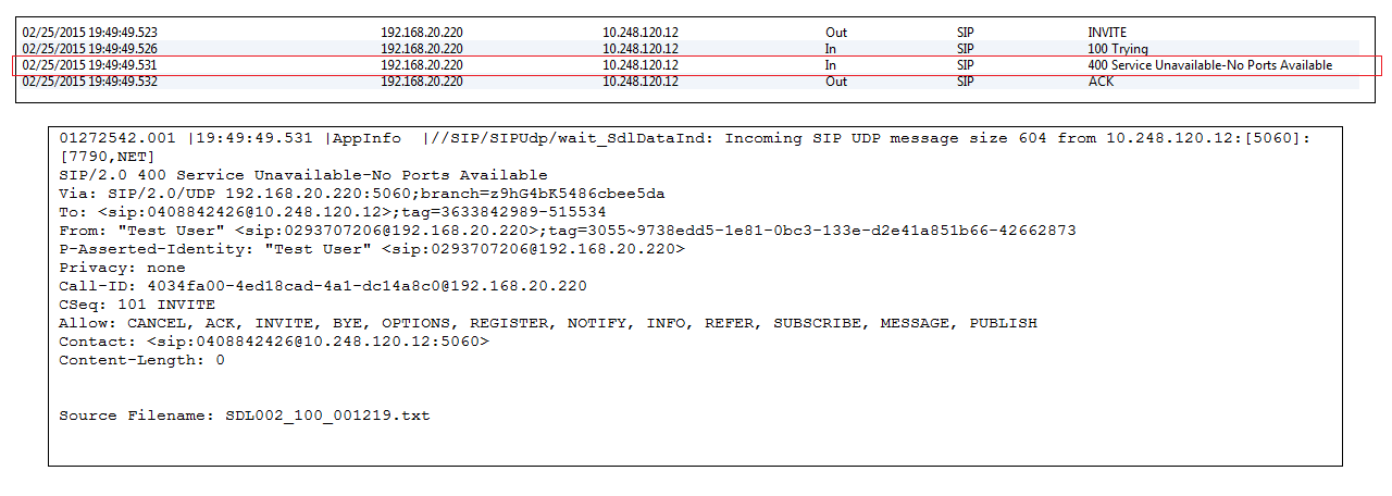
When calling outbound via SIP Trunk to ITSP you receive a 400 Service Unavailable-No Ports Available error after receiving the TRYING packet.

SIP Trace - CUCM

This error may indicate an issue with Early Offer being disabled. Most ITSP’s expect the SDP in the initial SIP INVITE. If the SDP is missing, the ITSP can return the above error.

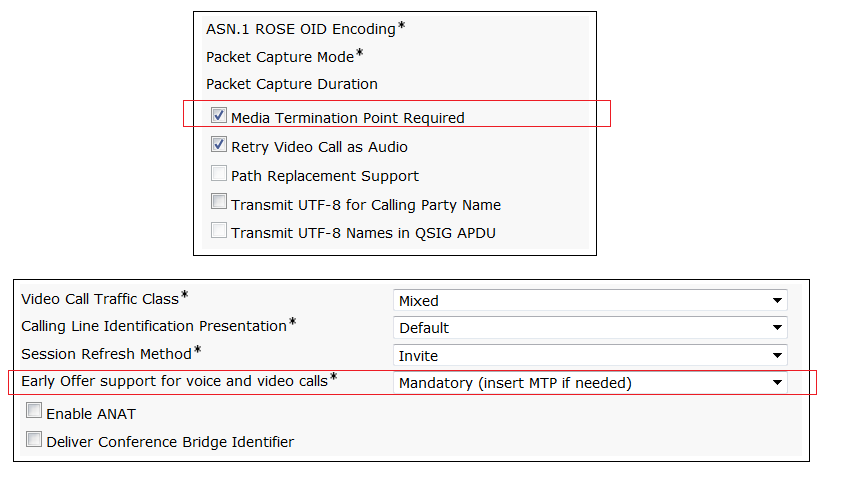
Simple fix is to enable Early Offer on Cisco CUCM. Below is a quick how to.

  1. Navigate to the SIP Profile configuration page and select “Mandatory (insert mtp if needed) for the Early Offer Support field.
  2. Navigate to the SIP Trunk configuration page and select “MTP Required”.
  3. Reset SIP Trunk.

CUCM Sip Trunk and SIP Profiles

Dec 16

CUCM and IM&P Integration with SRV Records

For us Cisco techs, one of the more often than not nowadays is that have to deal with the MS world of DNS (AND Certifciate Architecture… I’ll talk about this in later articles). I’ve had a fair bit of experience with DNS in the past, so I thought I would just share a little about integrating CUCM with IM & Presence using SRV records both ways to support CUCM Clusters and IM & Presence Clusters for high availability.

DNS Configuration

Create A (Host) Records

CUCM DNS A Records

Type Hostname IP Address
A cucm01.uplinks.com.au 192.168.0.20
A cucm02.uplinks.com.au 192.168.0.21

IM&P DNS A Records

Type Hostname IP Address
A imp01.uplinks.com.au 192.168.0.30
A imp02.uplinks.com.au 192.168.0.31

Create SRV Records

IM&P Cluster Name: imp.uplinks.com.au

Type Identifer Protocol Weight Priority Host
SRV _sip _tcp 10 10 imp01.uplinks.com.au
SRV _sip _tcp 10 10 imp02.uplinks.com.au

CUCM Cluster Name: cucm.uplinks.com.au

Type Identifer Protocol Weight Priority Host
SRV _sip _udp 10 10 cucm01.uplinks.com.au

Verify Records via NSLOOKUP

>  set q-all
>  _sip._tcp.imp.uplinks.com.au
>  _sip._udp.cucm.uplinks.com.au

The above should output the following results.

-        The SRV Records and their target hosts
-        An A record for every target host identified in the SRV record.

CUCM Configuration

SIP Trunk

  1. Navigate to Device, then select Trunks
  2. Select Add New
  3. Select SIP Trunk for Trunk Type
  4. Select Next
  5. Complete the details of the SIP Trunk as per normal.
  6. Under SIP Information, check the box  Destination Address is SRV

Note: When the checkbox is ticked, CUCM changes the outbound SIP protocol from udp to tcp.

  1. Type the IM&Presence Cluster Name. (imp.uplinks.com.au)
  2. Select Save and then reset the Trunk.

Configure SIP Publish Trunk

  1. Navigate to the Service Parameters, then Cisco CallManager.
  2. Find “IM & Presence Publish Trunk”
  3. Drop the arrow down and select the above SIP Trunk.

 IM & Presence Configuration

SRV Cluster Name

  1. Navigate to Service Parameters, then Cisco SIP Proxy.
  2. Find “SRV Cluster Name”
  3. Type the IM&Presence cluster name (imp.uplinks.com.au)
  4. Select Save

Presence Gateway

  1. Navigate to Presence, then Gateways.
  2. Select Add New
  3. Select CUCM for Presence Gateway Type.
  4. Type a Descriptive note.
  5. Type the SRV Record for the CUCM Cluster Name.

Note: Do not strip the SRV Identifier or Protocol. Example input would be _sip._udp.cucm.uplinks.com.au

Aug 30

Re-installing VMware ESXi where CUCM, CUC and IMP Publisher Servers Reside.

Under certain circumstances there may be a required to remove the underlying ESXi Host install and re-install maybe the same ESXi version or an updated version. One use case I can think is if the Server build was not originally built to Cisco Specifications that is incorrect Disk Numbers, Memory, CPU requirements, block size RAID configuration etc. The Cisco TAC Team will not support an independent Server Build unless the exact Server Design Specifications are met.

I will walk through such a case to reinstall an ESXi Server where the Publisher Servers reside, including CUCM, CUC and IMP.

Scenario: Single ESXi Host, Single Local Datastore, ESXi Host maintains the CUCM Publisher, CUC Publisher, IMP Publisher and the ELM Server.

Objective: Install additional Hard Disks, reconfigure RAID according to Cisco Specifications. Reinstall ESXi (same version) onto the first Logical Drive, and then look to reinstate the UC Application Servers.

First we will need to examine the current ESXi Server Build, networking parameters and general system parameters including DNS Servers, NTP, Domain Name, and License ID. Document the configuration parameters, so we can apply the same settings after the install the ESXi Host.

Failover the Publisher Servers to the Subscribers (if you have subscribers). Test UC functionality to ensure the Business can still operate as per normal.

Remove the Publisher Servers from Inventory (not Delete from Disk). In this case, I have access to an NFS Share, so I configured an NFS Datastore. In other cases, there may be iSCSI or FCP available. We basically just need another datastore that will be ‘safe’ for our vmx and vmdk files to be store while we complete the process.

Once the NFS Datastore is attached and the Virtual Machines have been removed from the Inventory we can Browse the Local Datastore, right-click on the first Folder (CUCM Pub) and select Move. Browse to the NFS Datastore and select the appropriate folder to store the CUCM Pub folder and files. This will start to move the CUCM Pub files to the NFS Datastore, this may take up to 2 hours.

Repeat for the CUC Pub and the IMP Pub. I prefer to separate the streams and not move the entire datastore in one move. I find it more efficient to have multiple streams. It’s really just a personal preference.

By now all the Virtual Machines folder/files are being moved to another datastore. Go grab a coffee.

Ok so all files have been moved the NFS Datastore, and you have checked the files are indeed n their correct location. We can no go ahead and shutdown the ESXi Host.

Make the appropriate hardware changes, let it be memory, cpu or Hard Disks and boot the Server up.

Upon boot up we will need to reconfigure the Arrays and Logical Drives. So hit Crtl-H during the Cisco Splash screen. This will direct you to the Array Configuration utility. Delete the existing Logical Drives and start the wizard to configure the Array and Logical Drives.

You must follow the Cisco Server Design Guide exactly. You will need to find what server spec you need to reference. In this case I need to create two logical Drives backed by RAID 5. I have 18 Disks, so 9 Disks per Logical Drive. I go ahead and configure the required arrays and logical drives. Reboot the server when complete.

I have previously downloaded the correct version of ESXi and is in an ISO format. I remotely connect to the CIMC Console and start-up the KVM. I click to the Media Tab in the KVM and map my ESXi ISO to the server.

I force the Server to boot from the ESXi ISO file and start the ESXi Install.

Using CIMC’s KVM utility login into the ESXi Console and configure the base parameters need to connect to the ESXi Host via the network. Details include selecting the correct VMnic, IP Address, Subnet Mask, Gateway, DNS Servers, Domain Suffix, and Hostname. Save and restart the Management Network.

Using your vSphere Client, connect and log into the ESXi Server. Complete the configuration according to your notes take in the initial information gathering phase.

Attach the NFS Datastore storing the Virtual Machines and proceed to move the Virtual Machine folders/files back to the Local Datastores. Again I prefer to have three data streams one for each Publisher Server. No go grab another well-deserved coffee as the transfer process to a VMDK Disk takes a touch longer than going to NFS storage.

Ok, once all the Virtual Machines have been successfully moved back across to Local Datastores, we can proceed to add the Virtual Machines to the Inventory. We don’t need the OVA files again and the vmx file contains all the original system settings for the Virtual Machines. We will browse to the Local Datastore where the Virtual Machine is now stored. Browse into the Virtual Machine folder, and right-click on the vmx file. (hostname.vmx). Select Add to Inventory. This adds the Virtual Machine back in the Inventory ready for powering on.

Power on the Servers, VMware will more than have you answer a question before permitting the Virtual Machine to be powered on. The question asks “was this Virtual Machine Copied or Moved” Select Moved. The Virtual machine will now power on.

Run all your standard UC Application tests to ensure the system is fully operational.

Last Step. Since we have effectively moved our ELM Server to a new Host, all the UUID information etc has changed. The ELM Server will still show the original licenses, however, they licenses will not be applied to the Publisher Servers. The ELM Server will be running in Demo Mode. 60 Day Grace period. The error complains about the Publishers already being managed by another ELM Server. There are commands on the CLI to clear the ELM Server connection in CUCM Pub and CUC Pub. However in this case, we need to Log a Cisco TAC Case and request to re-host the ELM Server. You will need to supply Cisco with the Original License files and the License Request file. Upon receiving the new License File, upload and sync all Publisher Server to ELM. In some case, you will need to remove the Publisher Server sin ELM first, and then re-connect the Publisher Servers. Log into the CUCM Pub and CUC Pub and ensure the Licenses have sync’d across successfully.

Job done.

Aug 10

Cisco Prime Collaboration Manager v10

Cisco have release the Video Data sheet for Cisco the Prime Collaboration Manager 10. This product is shipped with all v10 deployments and includes Cisco Prime Collaboration Assurance and Provisioning Manager. Also includes Analytics for an additional cost. The Collaboration Manager allows Voice Administrators to effectively monitor the health of their UC Environment and provides troubleshooting tools to resolve voice related issues quickly. One other big plus for me is the inclusion of being able to audit changes in Call Manager. Now Voice Administrators can delegate voice MACDs to helpdesk staff and review actual changes made to ensure changes are completed correctly.

I’ll write up configuration snippet in future blogs.

Jul 10

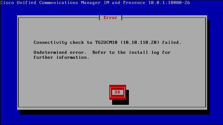
Cisco IM&P Server Install Fails – Connectivity Check to CUCM Publisher Fails

A slight change to the way IM&P is added to the CUCM Infrastructure in version 10. The IM&P Server is now thought of like a Subscriber in the CUCM Environment as it so tightly integrated in CUCM. So before you install IM&P Server, you will need to add the server to CUCM first, just as you would a CUCM Subscriber.

CUCM -> System -> Server -> Add New

Server Type will be CUCM IM and Presence, then enter the required details for IP Address and Presence Domain.

Now you can go ahead and install the IM&P Server.

Cisco IM&P Install Error

Jun 20

Finding and Changing the Default Directory URI Partition

By default Cisco CUCM 10 includes a system partition called “Directory URI”. All SIP URIs are placed into this partition automatically.

As this is a system partition, it cannot be removed from the system, however you can specify another partition where all SIP URIs can be automatically placed into.

System -> Enterprise Parameters -> Directory URI Alias Partition. Drop the menu down and select a partition you would like the SIP URIs to be placed into.

As you can see I have selected the partition called INTERNAL_PT for my SIP URIs.

Cisco CUCM - Directory URI Parameter