Sep 17

Cannot dial out to ISDN – Destination Incompatible

I recently came across a problem where I could dial mobile numbers via an ISDN 30, I could also use csim start command to dial out to local, national and mobile numbers. However I could not dial local, national or International numbers from an 8945 IP Phone.

Debuggin ISDN Q931 I received the following output:

Bearer Capability i = 0x8890A3
Standard = CCITT
Transfer Capability = Unrestricted Digital
Transfer Mode = Circuit
Transfer Rate = 64 kbit/s
Channel ID i = 0xA9839F
Exclusive, Channel 31

Error – Destination incompatible.

The solution was to configure the bearer capability on the voice-port for the E1. The 8945 was sending video capabilities to the carrier and the carrier was rejecting the call.

I entered the below command on the voice-port sub interface
Bearer-cap speech.

Jul 19

iDivert in CUCM 9.1

CUCM 9.1 has included a new edition of the iDivert feature. The legacy iDivert does still exist and is the Default setting in CUCM.

Legacy iDivert allows you to essentially divert incomming calls to your extension to your voicemail. The new iDivert now prompts you with a menu to either divert the call o your voicemail or to the voicemail inbox of the extension that may have forwarded the call to your extension.

Scenario, Phone A with extension 1001 had CFA set to Phone B with extension 1002. A call comes into Phone A which then is forwarded to Phone B. User at Phone sees that this call is originally for Phone A. By pressing iDivert, Phone B has the option to divert the call to either Phone A’s voicemail or Phone B’s voicemail. Phone B user elects to divert the call to Phone A’s mailbox by toggling to Phone A on the iDivert Menu and pressing Select.

NOTE: This will only work if CUC is configured to look at the first redirecting number rather thatn the last redirecting number. (image below) Otherwise the iDivert menu will only be able to divert calls to the their own voicemail inbox.

idivert


Jul 12

VoiceMail not Displaying on Jabber 9.2 with IMP 9.1

There are multiple reasons as to why Visual Voicemail will not display on your Jabber Client for Windows. I come across this little issue which had me going for a little while, so I though I’d post it up.

Like the title suggests, I could log into Jabber, makes phones calls, chat, listen to voicemail messages etc, however I could not see voicemails. Yes the VoiceMail icon was displaying fine. This particulare environment was not AD Integrated, now I know there are some articles out on the net saying that Jabber will not work unless its AD Intergrated, well thats not the case Jabber will work just fine and same with voicemails. You just need to make sure the ‘Web Application’ password in Unity COnnection is the same as the End User Password in CUCM. SO yes its a bit ore maintenance, so AD Integrated is the recommended method.

I checked and confirmed the UC Service for Mailstorewas correct, I removed this service and re-associated it. This UC Service is responsible for displaying the Voicemail Icon. So if you do not have the icon, this UC Service is probably misconfigured. I re enterd the users password into CUC for the ‘Web Application’, restarted Jabber and was getting the “Cisco Jabber is not connected to the your voicemail server’. I tested entering an incorrect password into the ‘Web Application’ password field, restarted Jabber. This time the error was ‘Unables to log into Voicemail etc’ So I knew the password was indeed correct.

I cleared the Jabber Voicemail cached from the PC, this is located under the username/AppData/Local/Cisco/UnifiedCommunications/Voicemail. Restarted jabber this made noe difference.

I then traced through the jabber client logs and noticed the following error message. “Failed for with error: returning error  NOT_AUTHORIZED : password must change, you must reset your password using the password reset URI” SO I had something to go from here. I logged back into the CUC Server and opened the User and select ‘Password Settings’, then dropped the box down to Web Application and low and behold the setting ‘‘ was checked. I unchecked this and Visual Voicemail starting working upon the next jabber restart.

So what this was doing was allowing the user to log into CUC, then CUC was prompting the user to change their password, however the jabber client doesnt have this ability so then CUC was throwing an unauthorized message back to Jabber and not allowing the user to view voicemails.


Jul 12

Direct Transfer to VoiceMail using CUCM with CUC

To give callers the ability to transfer phones calls directly to another callers Voice Mailbox in CUCM is quite a simple process, however it comes with a couple of gotchas that may have you pulling your hair out.

Start by first creating a CTI Route Point (CTI RP), this CTI RP will never register with an application or device, this is purely just to direct the calls to Voicemail.

So go to Device and CTI Route Points

Click Add New Device and complete the general details as you would normally, including Device Pool, MRGL, Location, CSS etc. CLick SAVE.

Now you will see Line [1] appear at the bottom of the page. This will where we will create  a new line/DN. So click on Line [1]. BTW we can configure multiple Lines on a CTI RP.

I prefer to user # as a prefix for Transferring Direct to VoiceMail. In the Directory Number Field enter #XXXX (In this example Im using a 4 digit numbering plan, if you were using a 6 digit numbering plan place 6 X’s  so #XXXXXX)

Give the Line a Description and Alerting Name.

**This is the gotcha. In the Alerting Name Field, Do Not include the word Voicemail. Even though CUCM will send the right digits in the right format and in the right fields ie last redirecting party number. However CUC will not treat this as a forwarded Call, but as a Direct Call, hence the caller will only hear the Opening Greeting for CUC.

Tick the Call Forward ALL check box and SAVE.


Now you call dial #(extension number) and the call will be directed straight through to Voicemail.


Jul 04

Video Conferencing Setup with 8941 phones

Given that businesses are opting for IP Phones with Video Cameras for point to point communications to get that face time when talking to each other they’ll also be interested in Video Conferencing, however the costs of an MCU for some is not a viable option. Cisco for some time now has included basic video conferencing functionality built-in to the PVDM3 Modules. The requirement is to have a PVDM3-128 or higher module. No you can’t have two PVDM3-64’s installed onto the Motherboard. Needs to be a single PVDM3-128 Module or PVDM3-256 module.

The video conferencing configuration is a two part process just with any Media Resource. First part is to configure CUCM Media Resources, and the second part is to configure the Vide Conferencing on the IOS Device.

In my example today I will be configuring Video Conferencing for Cisco 8941 IP Phones. So I’ll be configuring a Homogeneous video conference. There are two more conferences available which are a Heterogeneous video conference and a Guaranteed-Audio video conference. I won’t be discussing these two today. So Lets get started.

Start by visiting the Cisco.com website and navigate to the DSP Calculator. (http://www.cisco.com/cgi-bin/Support/DSP/dsp-calc.pl). We need to work out the percentage of the DSP Resources we need to reserve for Voice related services. Complete the required details and what type of conference, maximum sessions and conference participants. The calc will a DSP count of what you need for video services.

IOS Configuration

Voice-card 0
Set the dsp reservation for voice related services. Integer is a percentage.
voice-service dsp-reservation 40
Allow the DSP to share its resources
dsp services dspfarm

Configure the DSPFarm Profile

dspfarm profile 5 conference video homogeneous
codec g711ulaw
codec g711alaw
codec g729ar8
codec h264 cif frame-rate 30 bitrate 320kbps
maximum conference-participants 8
maximum sessions 4
associate application SCCP

*Note. Cisco 8941 IP Phones support H264 HD with CIF and 30p/s Frame Rate. I have also limited to the bandwidth to 320kpbs. This plus the G711 codec *64kkpbs is 384kpbs. (Default for inter-region for CUCM) Of course if the negotiated codec was G729r8 the bandwidth would 328kbps. This figure does not include headers information.

The maximum sessions and conference-participants parameters are dependent the how many resources you have allocated for Video. I’m using a PVDM3-128 and have allocated 60% to video resources so this allows me to configure 4 sessions with 8 participants or 2 sessions with 16 participants.

SCCP Configuration

sccp local Loopback0
sccp ccm 172.27.5.20 identifier 1 priority 2 version 7.0
sccp ccm 172.27.7.20 identifier 2 priority 1 version 7.0
sccp
sccp ccm group 1
bind interface Loopback0
associate ccm 2 priority 1
associate ccm 1 priority 2
associate profile 5 register VCFB_DC_HW

CUCM Configuration

Make sure all Locations and Regions are configured correctly.

Go to the Media Resource Tab and select Conference Bridge. Add New Select Cisco IOS Homogeneous Video Conference Bridge The Conference Bridge Name has to match the configure name under the SCCP CCM Group configuration. In my case its VCFB_DC_HW Complete the remaining details and you’re done.

Now just add the Video Conference to an MRG and then the MRG to an MRGL. Assign the MRGL to you Device Pool or to the phones directly. Now attempt to setup wither an ad-hoc or Meetme conference.

CUCM only supports Loudest Speaker Mode. So the IP Phones will display the person who is the loudest. CME also support Presenter Mode where you can statically fix the person who is displayed on the conference participant’s phones.


Jun 07

Class Maps Using NBAR

Below I will show an example of creating a class map that is to match SCCP, SIP and JTAPI using only nbar.

By default Class Maps use match-all statement. So if you you need to match multiple protocols, you must enter match-any when defining a class-map.

(config)#class-map CM-SIG
(config-cmap)#match protocol sip

(config-cmap)#match protocol skinny *NOTE we use the term skinny and not SCCP

By default nbar has existing port-mappings for SIP and SCCP(Skinny), but not for Jtapi. If we try to add match protocol jtapi, the IOS will throw an error.

To view the default nbar port mappings use the following command:

#show ip nbar port-map

We need to create a custom nbar port map for jtapi. To do this enter the below command:

(config)#ip nbar custom name tcp|udp portnumber

(config)#ip nbar custom jtapi tcp 2748

To verify the custom nbar port-map exists, enter the below:

#show run | i nbar

After this is defined in nbar, we can now use the match protocol jtapi in the class-map configuration.

(config-cmap)#match protocol jtapi

Note: To match traffic using nbar in class-maps, you do not need to enable nbar on any interface.


Jun 02

Migrating IP Phone Background Images

During CUCM upgrades we must ensure we migrate all the background images that were available on the existing CUCM to the new. The List.xml will tell us how many images and their file names are currently in use. For every type of phone, there is a List.xml file, tis is becuase of the different screen sizes for the phones. So ensure you  download all images and List.xml files for all your phone types.

1. Find and download the List.xml file for each of the phone types. To do this we need an SFTP Server on the network.

Log into the CLI on the Pub CUCM and for 7945/7965 phones type the following:

admin: file list tftp /Desktops/320x212x16

This verifies that there is a List.xml file and also contains image files.

Now download the List.xml. I have included the wizards steps to complete the transfer.

admin:file get tftp Desktops/320x212x16/List.xml

Please wait while the system is gathering files info …done.

Sub-directories were not traversed.

Number of files affected: 1

Total size in Bytes: 167

Total size in Kbytes: 0.16308594

Would you like to proceed [y/n]? y

SFTP server IP: 10.1.1.1

SFTP server port [22]: {ENTER}

User ID: cucm

Password: *********

Download directory: /

The authenticity of host ’10.98.231.126 (10.1.1.1)’ can’t be established. RSA key fingerprint is 85:27:6e:f4:e2:71:8a:c5:70:f4:38:c0:f2:aa:c9:76. Are you sure you want to continue connecting (yes/no)? yes .

Transfer completed

2. Lets open the List.xml File to view the contents.

- <CiscoIPPhoneImageList>

<ImageItem Image=”TFTP:Desktops/320x212x16/phone-pic-tn.png” URL=”TFTP:Desktops/320x212x16/phone-pic.png” />

</CiscoIPPhoneImageList>

From this xml we can see there is only a single background image. Each background image contain two files. The first referenced image is the thumbnail image 80×53 and the second is the Full 320×212 image.

3. Download the background images.

admin: file get tftp /Desktops/320x212x16/phone-pic-tn.png
admin: file get tftp /Desktops/320x212x16/phone-pic.png

4. Upload the List.xml to the new CUCM. If background images wre already configured on the new CUCM, you would need to download the List.xml and add the above XML lines to the List.xml file. This would then give the phone users additional background images to select from. We perform the upload action from CUCM OS Administration Page under Software Upgrades -> TFTP File Management

Ensure the Directory is /Desktops/320x212x16

5. Restart the TFTP Server for the background images to be displayed on the IP Phones. This is done on the Cisco Unified Serviceability Page -> Tools -> Control Center – Feature Services.

6. Select the background image from the IP Phone by selecting Settings -> User Preferences -> Background Images.

A full list of the exact background image sizes can be found on the Cisco.com website.

May 27

Call Control QoS – IOS

Just a brief note to mention QoS for call control and media flow on ISRs. Three areas are Dial Peers, MGCP Gateways (IOS Only) and SCCP controlled resources. Its important to understand where to find the QoS related configuration for each of the above not only for the CCIE Voice exam but for real-world projects aswell.

Dial-Peers

The default QoS markings are the same for both H323 (Default) and SIP dialpeers on an ISR. The RTP or Media is marked as EF, while the Signalling is marked at AF31. Remember Industry best practices for RTP/Media is EF and for signalling is CS3. To find this information on a Cisco ISR, enter the following command.

#Show dial-peer voice dialpeer number | i DSCP

Output from the above command:

ip media DSCP = ef, ip media rsvp-pass DSCP = ef
ip media rsvp-fail DSCP = ef, ip signaling DSCP = af31,
ip video rsvp-none DSCP = af41,ip video rsvp-pass DSCP = af41
ip video rsvp-fail DSCP = af41,

To change the default QoS markings, entering the Dial-Peer config mode and use the below commands:

  • ip qos dscp ef media
  • ip qos dscp cs3 signalling

I realise we are not changing the EF marking, but this is just to give you an example of where and how to change the markings.

You can find all the QoS DSCP Values and their relating Binary numbers if enter the ? after dscp:

(config-dial-peer)# ip qos dscp ?

<0-63>   DSCP value
af11     Sets DSCP to assured forwarding (af11) bit pattern 001010
af12     Sets DSCP to assured forwarding (af12) bit pattern 001100
af13     Sets DSCP to assured forwarding (af13) bit pattern 001110
af21     Sets DSCP to assured forwarding (af21) bit pattern 010010
af22     Sets DSCP to assured forwarding (af22) bit pattern 010100
af23     Sets DSCP to assured forwarding (af23) bit pattern 010110
af31     Sets DSCP to assured forwarding (af31) bit pattern 011010
af32     Sets DSCP to assured forwarding (af32) bit pattern 011100
af33     Sets DSCP to assured forwarding (af33) bit pattern 011110
af41     Sets DSCP to assured forwarding (af41) bit pattern 100010
af42     Sets DSCP to assured forwarding (af42) bit pattern 100100
af43     Sets DSCP to assured forwarding (af43) bit pattern 100110
cs1      Sets DSCP to class selector codepoint 1 (precedence 1)
cs2      Sets DSCP to class selector codepoint 2 (precedence 2)
cs3      Sets DSCP to class selector codepoint 3 (precedence 3)
cs4      Sets DSCP to class selector codepoint 4 (precedence 4)
cs5      Sets DSCP to class selector codepoint 5 (precedence 5)
cs6      Sets DSCP to class selector codepoint 6 (precedence 6)
cs7      Sets DSCP to class selector codepoint 7 (precedence 7)
default  Sets DSCP to default bit pattern of 000000
ef       Sets DSCP to expedited forwarding bit pattern 101110

MGCP Controlled Resources

MGCP has the same defaults as Dial Peers, so I won’t go in too deep. To find the what QoS values have been configured for MGCP resources enter the command:

#Show mgcp | i DSCP

To change the DSCP Values for media and signalling in MGCP, enter the following commands:

(config)#mgcp ip qos dscp ef media

(config)#mgcp ip qos dscp cs3 signalling

SCCP Controlled Resources

QoS default markings for SCCP are EF for RTP/Media and CS3 for signalling, so in effect SCCP meets the industry best practices. However dont assume these values are configured correctly for the CCIE Voice lab exam. SCCP QoS config is found in the SCCP CCM Group configuration.

#Show sccp ccm group 1

To configure QoS markings for SCCP CCM Groups enter the following:

(config-sccp-ccm)#audio dscp ef

(config-sccp-ccm)#signalling dscp cs3

I hope this clarifies a little for you, now knowing exactly where to go find and change DSCP Values for call controll resources on an ISR Voice Gateway.

May 23

LAN QoS Information for CCIE Voice Lab

Referenced Documents for studying

Recommended to read the following guides prior to Lab Exam:

  • Medianet  Campus QoS Design 4.0
  • SRND CUCM 7.0 -> Under Network Infrastructure Chapter
  • Enterprise Qos Solution Reference Network Design Guide Version 3.3

Basic QoS Marking

Per Hop Behaviour (PHB) splits the 6 most left bits in the ToS Byte into two. First half is the CS or IP Precedence bits, the second half is used for the Drop Probability. PHB uses EF, AF and CS terminology. DSCP spans 6 bits in the ToS Byte and is shown in binary format. ECN are the two right most bits in the ToS Byte

ToS Byte

Tos Byte : Reference from Cisco.com

Industry Defaults as it pertains to Voice

  • EF – DSCP 46 is used for Voice Traffic | Layer 2 CoS Map is 5
  • AF41 – DSCP 34 is used for Video | Layer 2 CoS Map is 4
  • CS3 – DSCP 24 is used for Voice Signalling | Layer 2 CoS Map is 3
  • Scavenger – DSCP 8 is used for malformed traffic ie worms | Layer 2 CoS Map is 1

3750 Priority Queuing

Priority queuing is disabled by default and all queues are equal. The 3750 switch has 2 Ingress Queues and 4 Egress Queues. If Priority queuing is enabled for ingress/ egress queue the Egress Priority Queue is Queue 1 and the Ingress Priority Queue is Queue 2. The priority queue will empty first before any other queue is looked at.

DSCP PHB values are assigned to Queues, a DSCP PHB Value can only be assigned to one queue for the egress and ingress.

If conflicting ToS values exist between the Layer 3 and Layer2 headers, then the DSCP value is preferred over the CoS value on the 3750 Switch. Based on the DSCP value is what determines which queue the packet is to be placed into.

Priority-queue out interface command configures the Priority Queue.

Buffer and Memory Allocation

We can determine how much memory can be allocated per queue. ie. determine how big the queue can be. Memory allocation is Ratio driven. Eg. Queue 1 is configured at 10%, hence Queue 1 can used 10% of the memory that is assigned to the entire port (Reserved Pool).

The queue can utilise memory from the Common Pool buffer and/or from reserved buffers if they are not being used by other queues on the switch. This allows the queue buffer to expand over configured reserved buffer and up to the maximum allocated buffer for the queue.

Configured via the mls qos queue-set output qset-id threshold queue-id drop-threshold1 drop-threshold2 reserved-threshold maximum-threshold command. The reserved-threshold is the total reserved memory for the queue (100%/T3) and the maximum-threshold is the absolute maximum memory the queue can use including from the Common Pool memory

mls qos queue-set output qset-id buffers allocation1 allocation2…allocation4. The total amount of allocated buffer equals the Reserved Pool. Unused memory from the reserved pool is returned to the Switch Common Pool for other queues to potentially use.

Weighted Tail Drop

3750 switch has 3 WTD Thresholds for each queue. T3 (Tail Drop Threshold 3) is always 100%. eg. Because the memory allocation for the queue is full, then 100% of the incoming frames will be dropped.

This leaves 2 configurable WTD Thresholds. We can configure any threshold for each queue. Eg. T1 for Q1 equals 40%(400 frames), T2 for Q1 equals 60% (600 frames). If we were to apply this to PHB, we configure PHB to WTD Thresholds. So if we configured CoS 0-3 in Q1/T1 then when the memory allocation for Q1 reaches 40%,the switch will proceed to tail drop CoS 0-4 traffic, but not touch other PHB traffic configured in the queue for example EF Q1/T2 which is CoS 4-5 or Q1/T3 which is CoS 6-7.

Weighted Threshold Drop

Reference from Cisco.com

Note: T1 and T2 can be equal to T3

Shaped Round Robin (SRR) & Shared Round Robin (SRR)

SRR Controls the rate at which packets are sent. The SRR on the ingress queue sends packets to the Stack Ring and the SRR on the egress queue sends the packets to the egress port. The ingress Queue only supports Sharing Round Robin. The egress Queue supports both Shaping and Sharing Round Robin.

Shaped mode guarantees a percentage of bandwidth for the egress queue. The egress queue is rate-limited to the configured amount. Shaped traffic does not use more than its allocated bandwidth even if the interface/link is idle.

In shared mode, the queue shares the bandwidth among themselves. The bandwidth is guaranteed but not limited for each queue. Ie. If the interface/link was idle a single queue can use more than its configured bandwidth amount.

Interface commands:

  • srr-queue bandwidth share weight1 weight2 wieght3 weight4
  • srr-queue bandwidth shape weight1 weight2 wieght3 weight4


May 07

Deploying Ironport Cisco Web Security Virtual Appliance

Prerequisites

  • Download OVF file from Cisco.com. Use a CCO login that has access to the WSA download section.
  • Ensure you have received a PAK License ID from Cisco. This should have been received via email
  • Generate a License file from cisco.com/go/license

Installing Ironport Cisco Web Security Virtual Appliance

  1. Log into your VMware VCentre Console. Deploy OVF file

2.   Browse to OVF file location

2

3.   Specify Name for the Device. Eg vWSA-01

4.   Specify the Datastore to install the Device.

5.   Select ‘Thin Provision’. Default is Thick provision, this will consume 1TB of data, includes whitespace.

5

6.   Map the Network to the correct Port Groups.

6

7.   Power on the VM

8.   Default username and password

U: admin

P: ironport

9.   Set the Time on the vWSA

Settime

MM/DD/YYYY HH:MM:SS

10.   Commit changes. Commit cmd

11.   Copy license to vWSA. FTP to vWSA device and browse to the ‘Configuration’ Directory. Copy the license.xml to this directory.

12.   Upload License. SSH to the vWSA device. Type ‘loadlicense’ select option 2 to upload from xml file.

12

13.   Accept License Agreement

14.   Browse to the GUI. https:// 192.168.0.2:8443 or http://192.168.0.2:8080

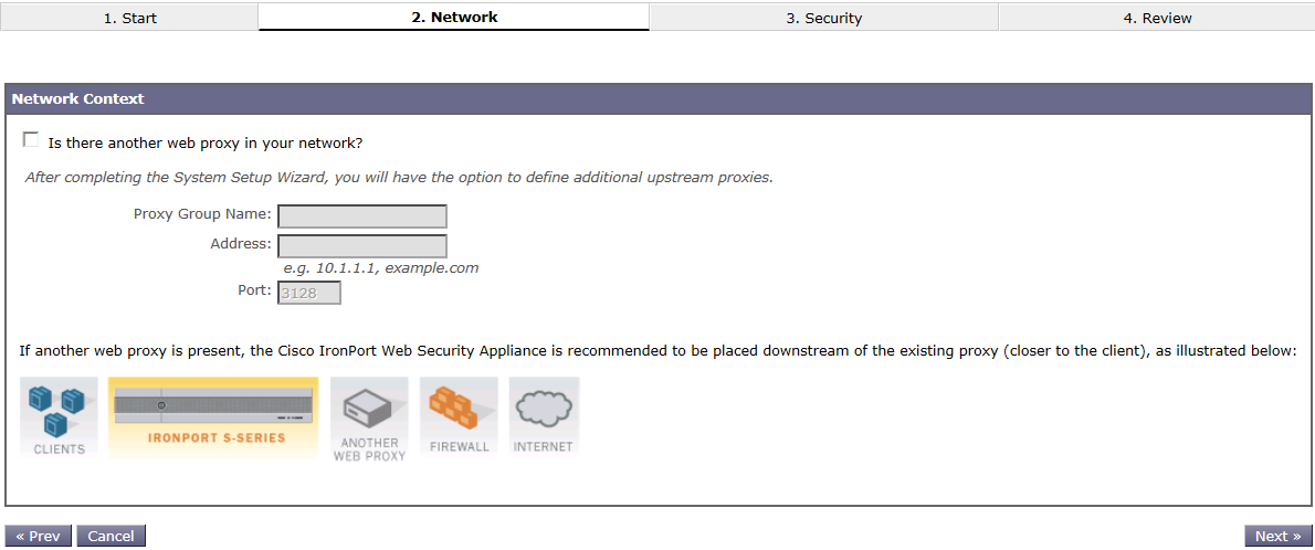
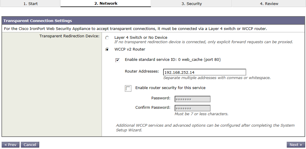
15.   Run System Setup Wizard via the System Menu.

15a

15b

15c

15d

15e

15f

15g

15h

16.   Click ‘Install this Configuration’ to complete the setup wizard.

This is just the initial install steps for Ironport. I’ll write up some more posts on Ironport configuration in the future. There are a lot of variations to the configuration.