I’ll be going through the process to configure Call Recording using Cisco Mediasense with the UCCX Finesse Agent. The Mediasense Server itself requires a server license plus Media Port licenses, the port licenses can be either Audio Only or Audio/Video. As it stands the previously mentioned licenses are a ‘right use’ license. Cisco is trusting partners and customers to apply the correct amount of licenses for their installed instances. The Contact Centre though is different story. Additional Call Recording licenses need to be purchased as the Contact Centre product controls the call recording streams. These licenses must be uploaded to the Contact Centre server. We’ll discuss this further below.
Mediasense seems to work as expected and can record calls in a variety of ways (Phone, Gateway, CUBE) which gives flexibility to various customer requirements. The feature set however needs some more work. I found the Authorisation/Security component of Mediasense Call Recording is very basic compared to other products on the market. Hopefully Cisco is looking at RBAC for future releases.
Lets get to the configuration part, we’ll start with CUCM.
Create an End User either directly on CUCM or via Active Directory. Mediasense requires its API Users to be End Users in CUCM and not Application Users. When deploying Mediasense the initial wizard will ask for this Users details.

The End Use in my case ‘mediasense’ is required to have the AXL Role and be a member of the Standard CCM Admin Users group
 CUCM communicates with the Mediasense server via a SIP Trunk, even with gateway recording it’s the CUCM Server that will send the INVITES to the Mediasense server.
So go ahead and setup the SIP Trunk configuration. We’ll start with the SIP Profile.
I always find it easier to copy the Standard SIP Profile then make any changes necessary, that way all SIP Profiles are isolated from each other making future changes easier with less impact to other SIP services.
In the Mediasense SIP Profile, I’ve enabled SIP Options. If I was to have more than one Mediasense server, this is where SIP Options would come in useful. CUCM polls each Mediasense server to determine if its down or up, and will only send INVITES to a Mediasense server in an operational state.
 The default SIP Trunk Security is good enough for Mediasense. The main field to take not is the Outgoing Transport Type.. This must be TCP. So worth to check this setting. If its been set to UDP, then create a new SIP Trunk Security Profile.
 Create a new SIP Trunk with the basic settings. Provide good descriptions and select the SIP Profile and SIP Trunk Security profile as created above. Can use either the IP Address or FQDN for the Destination. Port is SIP standard 5060.

 Create a Route Pattern for the Call Recording profile to match. I’ve just selected the Mediasense_Recording SIP Trunk as the destination. You can also use Route Lists and Route Groups. Ive also placed this route pattern in the Global SYSTEM partition. You can create a new partition for Call Recording and place the pattern into this, then just allocate the Call Recording profile the CSS that has access to the specific partition.
 Create a Recording Profile selecting the pattern defined above in the Route Pattern step. Also select the appropriate CSS that has access to the partition the call recording pattern is in.
 Now we jump across to the Phones. In this blog I’ll be using the Phone Preferred architecture, hence the phones will be forking media to the Mediasense server. For this to happen the phones need to have the ‘Built In Bridge’ enabled. This is also a global setting if wish to blanket all phones.
Repeat the below steps for each phone/line that will have recording enabled in the Contact Centre.
Enable the Built In Bridge. Save and Apply Config.
 Go to the Line of the Phone (or for the Device Profile). Navigate to the Line Settings for this Device area and select the Recording Option, Recording Profile and the Recording Media Source. In my case, I’ve enabled recording with Selective Call Recording enabled. The alternate option is automatic call recording. (Always On). In this blog, I want to control the Call Recording via UCCX Workflows.
 Optional is to have a beep play to let the call party’s know the conversation is being recorded. Default is set to off.
 Also optional is to assign a Call Recording Softkey to the phone or device profile. If pressed during a conversation, the CUCM actions to the call recording and not UCCX/Finesse.
 Mediasense Configuration
The install for Mediasense is fairly straight forward. After deploying the correct OVA for your environment size and going through the initial CLI configuration wizard configuring IP Address details, DNS Servers etc Its time to browse to the Web GUI.
Log into the Web GUI using the user credentials configured in the CLI wizard. The first couple of screens are more or less notifications and information about mediasense. Click next through these.
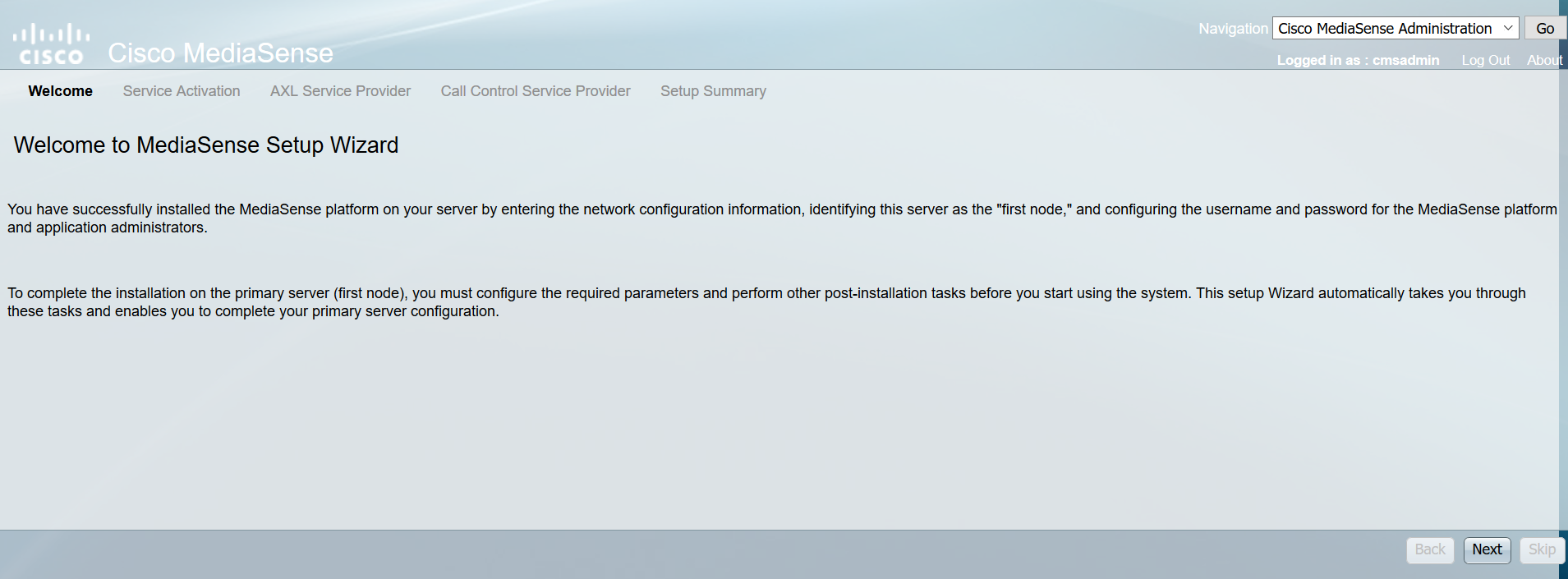
 The AXL Service Provider is the End User created during the CUCM configuration phase. The AXL provide IP Address is of course your CUCM Server (ensure you have the AXL Service activated)
 The Mediasense will discover all the Call processing Servers in the environment. Funny enough, it also discovers the Presence Servers?
 Click next through the summary page and you will end up at the Administration Console of the Mediasense server.
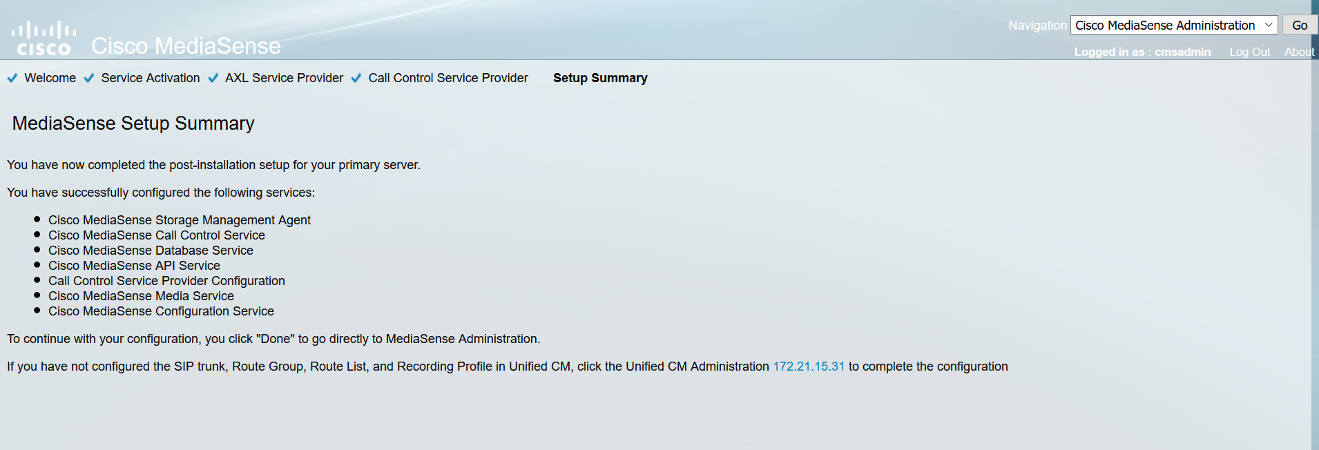
 Navigate to the Cisco Finesse Configuration window and enter the UCCX Servers is the appropriate field. Ensure to FQDN for the UCCX Servers.
 Navigate to the Mediasense API User Configuration window and search for the End User created in the CUCM phase. In my case its mediasense. Add the End User to the Mediasense API Users. Also, from the screen, add the users in that shall have GUI access to the search and play browser.
 UCCX Configuration
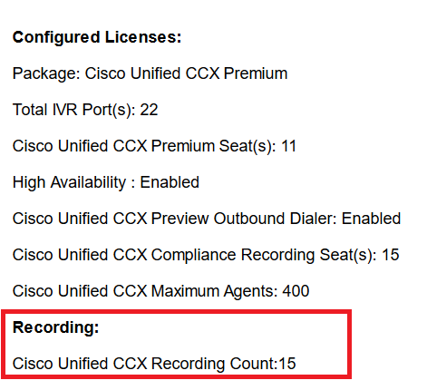
Start by uploading the Call Recording Count Licenses for CCX. **NOTE Part Number required is “INCREMENT CRS_REC_PORT”
After uploading the licenses, the License Display Screen should look similar to the below.
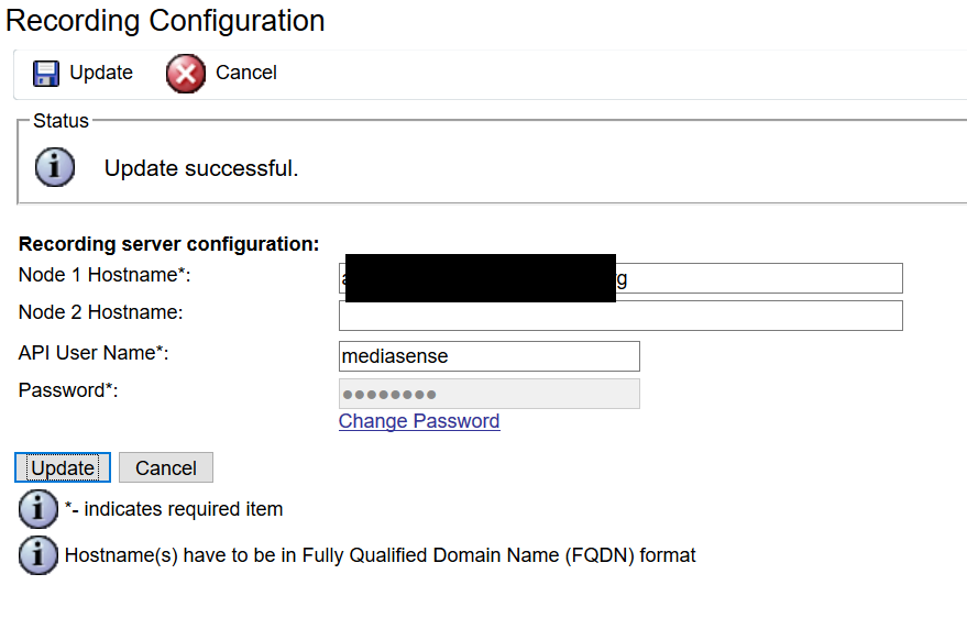
Add the Mediasense Recording Server and API User to the CCX Server. This user was added to the Mediasense API User list in the Mediasense configuration phase.
UCCX Script
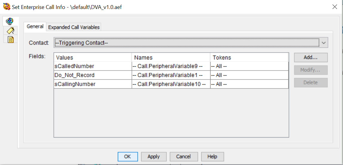
Now seeing that I’m going a step further with this configuration due to the customer requirements. I’ll add it all in for you to see. In this particular case the customer required to have an ‘opt-out’ menu for call recording. Hence the caller could select IVR Option ’9′ and essentially opt-out of call recording. For this to happen, we need to first create some script variables. I created a variable called ‘Do_Not_Record’ with a value of ‘Do Not Record’ and linked this String to Call Variable 5. I could’ve created an ECC Variable, however, Im working with UCCX 10.6 at the moment.. And there is a current bug preventing ECC Variables from being used in the Finesse Workflow filters.
I have also create a script variable called ‘Record_Call’ with a value of ‘Record Call’ and linked to Call Variable 2.
See below for Call Variable image along with script insertion.
 Finesse Administration
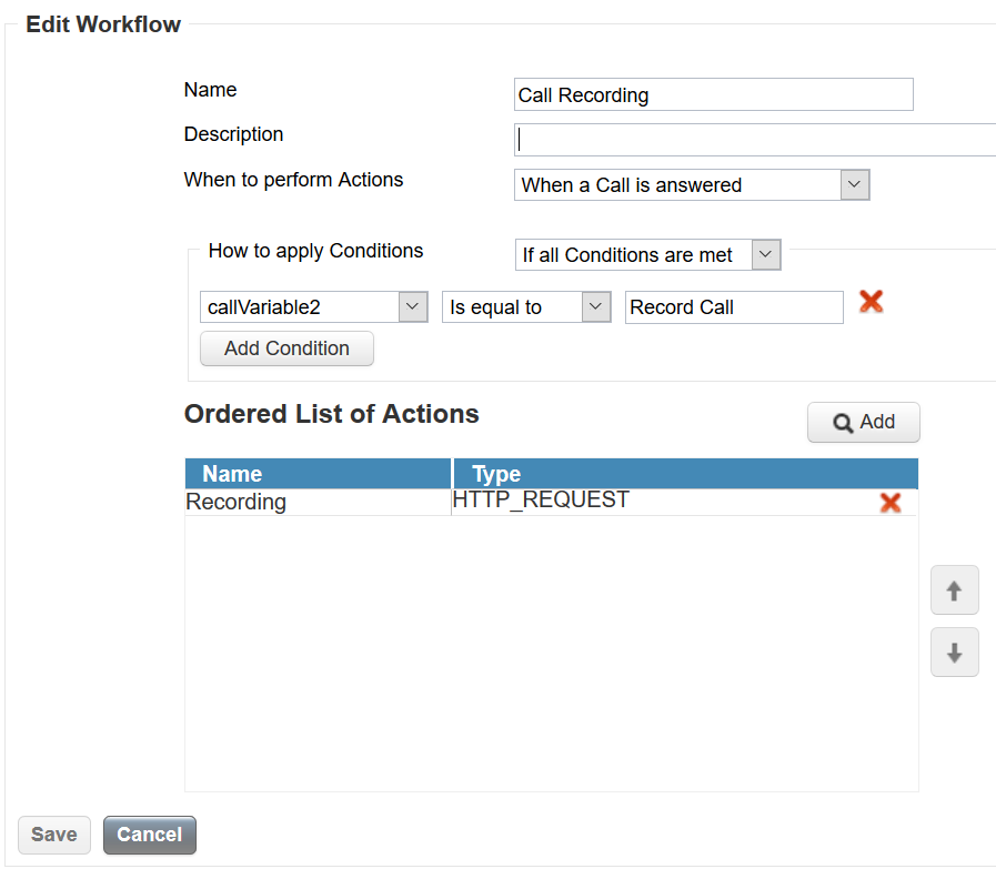
We need to now create a workflow and utilise the variables created in the previous step. First step is to create a workflow action. See below for the workflow action created, this follows the standard procedure for invoking Mediasense.
 We then need to create a Workflow filter or match condition. I’ve created a filter or match condition for Call Variable 2 (value = Record Call).
Hence the match condition is when the ‘Record Call’ is presented via Call Variable 2. Relating this to the above script, is when a caller does not press IVR option ’9′ to opt-out, the value ‘Record Call’ is inserted into Call Variable 2.
Add the workflow action and click SAVE.
 No we can add the Workflow to a Team. Navigate to the Team configuration page and select the appropriate team. Now click the Workflow menu (lower right).
Click the Add button and browse or select the Workflow required.
 Also worth mentioning is the MS AgentInfo gadget. This gadget inserts/passes metadata to the Mediasense engine. I’ve given two examples below, the first example is a call recording without the AgentInfo gadget, and the second example being with the MS AgentInfo gadget.
To apply the MS AgentInfo gadget, navigate to the Desktop layout configuration page (either Global or Team based). Add the below lines to the Agent Desktop layout. Agents then need to log out of Finesse then back in.

 NOTE: Mediasense Play Back requires Java 1.7+.
Without the MS AgentInfo Gadget deployed in Finesse
 With the MS AgentInfo Gadget deployed in Finesse
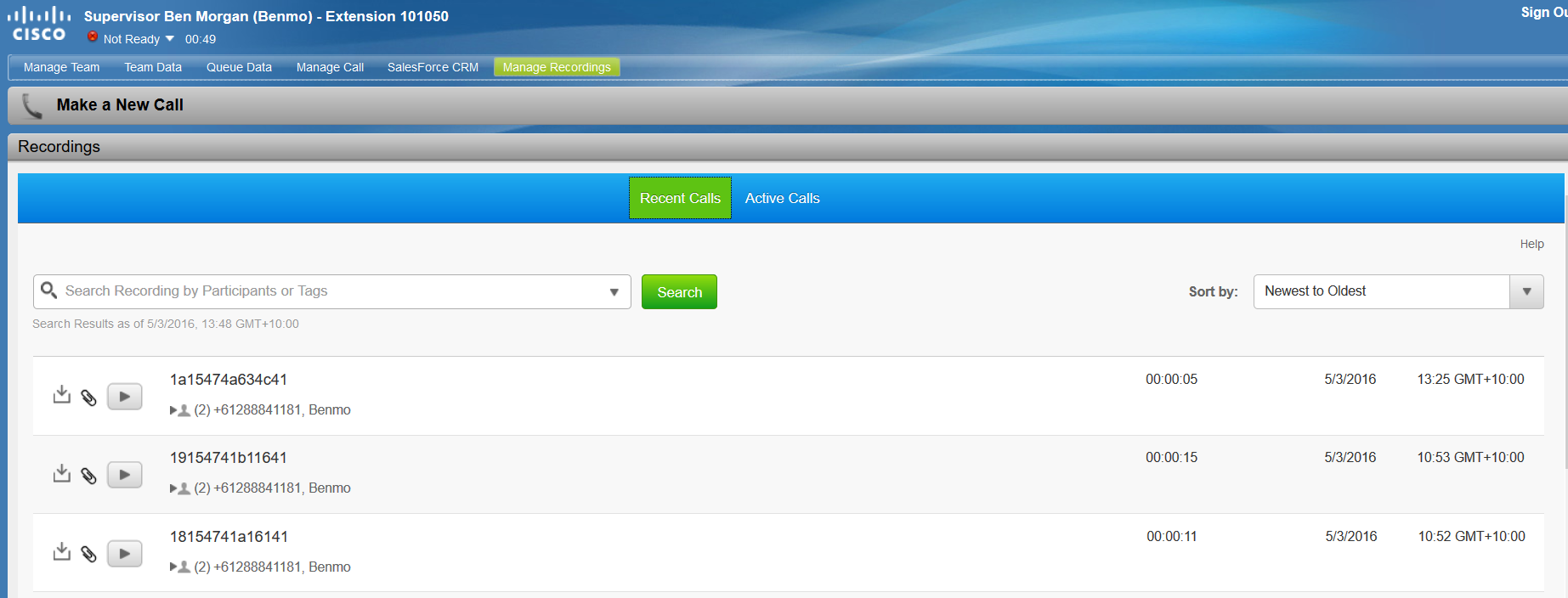
 OPTIONAL: Unhide the Mediasense gadget for the Supervisor to allow the Supervisor to search and play call recordngs from the Finesse Agent window.
 Media Resources -> Mobile Voice Access
 Device -> Device Settings -> Remote Destination Profile


